
The best way for a new user to begin is to select ‘New beam’ and run the beam wizard. This will take you through step by step the key properties that form a beam within the software. FBEAM has a dynamic built in help function that provides a user with guidance on the various functions available as necessary.
FBEAM works by combining a series of individual properties (section size, load combinations, cell layouts et…) into one element; beam failures can be overcome by making changes to these individual properties. For example if the beam was failing in deflection, the user should double click on “section” in beam properties and increase the section depth accordingly.
Error: This is an error in the data entry that must be corrected before the beam analysis or design entry can be completed.
Warning: A warning will appear when a decision made during the design process means that an additional item may need checking to ensure an adequate design or that a decision may yield a design that is not optimum for manufacture.
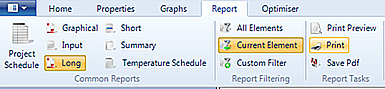
Reports allow the user to export their calculation results from the software either for a single beam or multiple beams. The user can create reports with the varying amounts of detail, dependent ontheir specific requirements.
Fbeam is a free software tool designed to support the design of new Fabsec beams. The software includes built in restrictions on section geometry that take into account design, procurement, and fabrication considerations. These constraints help ensure beams are not only structurally efficient but also practical to manufacture and deliver. If you have any project specific questions or require further guidance, please contact us at support@fabsec.co.uk.
 EN1993 – 1 1:2005 C1.6.2.6(6.18)
Where
 is the Shear Area.
 is the design yield strength.
 is the material factor = 1.0
The shear area may be taken as follows:
Welded I, H and box sections, load parallel to web, 
Welded I, H and box sections, load parallel to flanges, 
Axial force in a composite beam is conservatively considered to be taken by the steel beam only.
For the combination of axial force and bending, Fbeam uses the method outlined in BSEN1993-1-1:2005 Cl 6.2.9.
If you apply an additional point load onto a beam, the software assumes this is applied to the top flange and a local web bearing and buckling check is required to determine if stiffeners are required. This is not carried out within software.
Fbeam 2016 does not currently facilitate the design of tapered sections. This is on our development list.


